
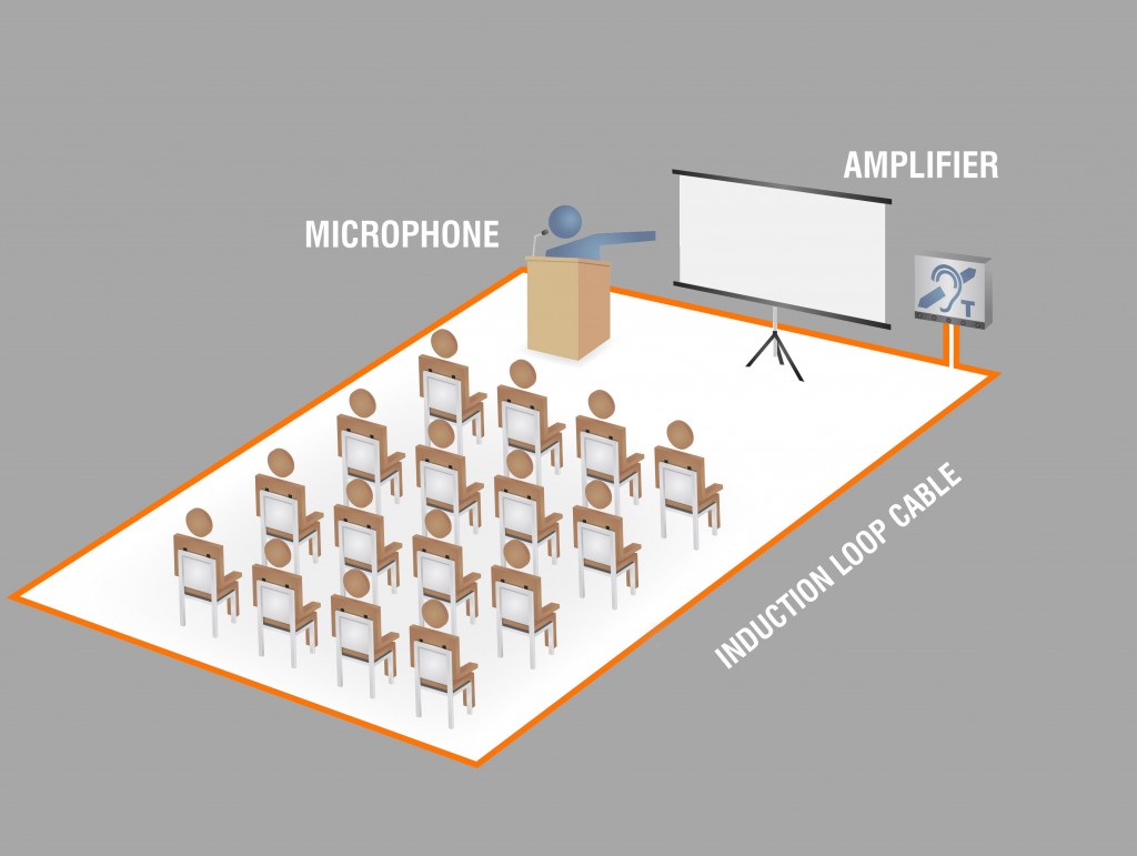
Auris Hearing Loops maximize the benefit of hearing aids fitted with “TeleCoils”. The T-Coil receives the wirelessly transmitted signal from the hearing loop: most hearing aids ( 70% +) are already fitted with T-Coils.
According to Lee Ramsdell of the Canadian Hard Of Hearing Association (CHHA), use of the microphone alone in a hearing aid has an optimal distance of only 1 – 2 metres. Beyond this distance from the sound source, users often experience unwanted background noise or echo which makes it difficult to stay engaged. An Auris hearing loop transmits sound directly to a t-coil equipped hearing aid, eliminating these problems.
The sound source (mic, TV, soundtrack, mp3 etc) is wirelessly transmitted directly to the recipient’s hearing aid, thus eliminating the problems of:
“The introduction of the Auris Hearing loop has made a remarkable, and positive, difference for our many patrons. I hope that you will be able to use the Auris Hearing Loop system in other public buildings as it will be a benefit to so many people”.
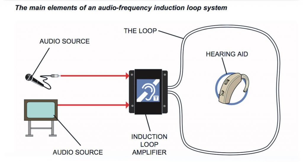
It’s elegantly simple! The dedicated Auris Hearing Loop amplifier converts an audio signal (eg. a microphone, TV, soundtrack, MP3 etc) into a magnetic signal, delivered via thin cable or copper foil usually installed around the perimeter of a room or as a figure of ‘8’ under the floor.
The transmitted loop signal is received in the recipients own hearing aids when they switch on the ’Tele-Coils’ (or ’T-Coil’), which converts the magnetic signal back into a crystal clear audio signal. No headsets to collect/return. No hygiene issues. Completely discreet. But most of all, the sound quality delivered is always superior through a bespoke hearing aid rather than a generic ‘one-size-fits-all’ set of headphones as found in FM. Infrared or Bluetooth systems.
By the way, it is an entirely safe technology that has been used by all the other G7 countries for over 50 years, yet is relatively new to Canada!
What is a Tele – Coil (or T-Coil)?
A tele-coil (or t-coil) is a tiny receiver already found in most hearing aids. It picks up the audio signal wirelessly transmitted by the Auris hearing loop and delivers crystal clear sound directly to the hearing aid.
Do I already have a T-Coil?
Most hearing aids have t-coils already fitted. The problem is, that because Canada is the last country in the G7 to wholeheartedly adopt hearing loops, some audiologists neglect to discuss t-coils.
I repeat, If you have a hearing aid, the chances are that you already have t-coil, it just needs to be switched on!
If in doubt, contact your hearing clinic and ask them two simple questions:
1) Does my hearing aid have a t-coil?
2) How do I switch it on/off?
(Some t-coils are switched on/off by pressing or holding a button on the hearing aid itself, some are activated by a button on a remote control).If you are buying a new hearing aid or upgrading your existing one, request a model with a t-coil. It is a no-cost option. There is simply no reason not to have a t-coil.
– Churches & Halls
– Theatres & Cinemas
– Council Chambers
– Hotel Meeting Rooms
– Conference Centres
– Residential Homes
– Domestic Homes
– Booths & Counters
– Airports & Bus Stations
– Restaurants
– Vehicles
– Libraries
VERNON
General Community
Places of Worship
ARMSTRONG
General Community
Places of Worship
ENDERBY
General Community
Places of Worship
SALMON ARM & AREA
General Community
Places of Worship
KAMLOOPS
Places of Worship
KELOWNA
General Community
Places of Worship
WEST KELOWNA
Places of Worship
LAKE COUNTRY
General Community
Places of Worship
PENTICTON & AREA
General Community
Places of Worship
OLIVER
General Community
Places of Worship
VANCOUVER
General Community
VANCOUVER ISLAND & GULF ISLANDS
General Community
Places of Worship
ABBOTSFORD
Places of Worship
WILLIAMS LAKE
Places of Worship
SMITHERS
General Community
KITIMAT
General Community
TRAIL & AREA
General Community
Places of Worship
NELSON
General Community
CALGARY & AREA, AB
Places of Worship
SASKATOON & AREA, SK
General Community
Places of Worship
SAINT JOHN & AREA, NB
All 12 Expert Hearing Solutions in
BC, SK & Ontario
“The residents are extremely happy!. I recommend Auris Hearing Loops to any place/organization that has people with hearing aids. It will make a huge difference to their lives”. – Jerry Telier, Director, Vernon Restholm.
Auris Loops Systems need to be correctly specified and installed according to the unique requirements of your environment. Considerations include the size of the room, the length of loop cable required and the cost of installing and optimizing the system.
The prices below include the cost of the loop amplifier and loop cable, but do not include installation labour. Most loop systems can be installed in a single day. Qualified installation engineers usually charge in the region of $65 – $90 per hour. These prices are strictly ‘ballpark figures’, but these may vary according to the considerations above.
PDA1000: Up to 900m sq – $3000.00 (Theatres, Conference Centres etc)
PDA500: Up to 500m sq – $2200.00 (Medium sized Churches, Meeting Rooms etc)
PDA200: Up to 200m sq – $1500.00 (Smaller Churches, Residential Homes etc)
DL50: Up to 50m sq – $400.00 (Home, Domestic Lounge)
CL1: Counter Loop – $500.00 (Airports, Libraries, Banks, Retail etc)
PL1: Portable Loop – $500.00 (Restaurants, Family Gatherings etc)
VL1: Vehicle Loop – $400.00 (Cars,Vans,Tour Buses etc.)
Loop systems can be very cost effective when compared with other assistive listening technologies such as FM, Infrared and Bluetooth.
Loop v. FM Cost Comparison A Real World Example
Let’s take the real world example of The United Church in Winfield, BC. The sanctuary measures 50’ x 40’ and has at least 10 x people that would benefit from hearing assist technology, (probably more in the future as hearing loss predicted to increase).
FM system (1 x transmitter and 10 x receivers) $2349.00
20 x AA Batteries @ $0.79c each changed monthly $200.00 per year
Additional receivers $94.00 ea
Loop System
PDA 200 loop amp, cable & Installation $1970.00 (no additional costs)
Zero additional cost of batteries or additional receivers.
Additional Loop Benefits Above & Beyond The Cost Advantage
More Discreet – Users use their own hearing aids not headphone.
More Hygienic – Users use their own hearing aids
More Convenient – Nothing to collect / return.
Zero Maintenance – No batteries to change, headsets to clean or service.
Superior Sound – hearing loss adjusted aids sound better than generic ‘one-size-fits-all’ headphones
Unlimited users for no extra cost. No embarrassing situations when extra receivers are required but not available. No one is excluded.
Control. Hearing aid users can adjust their volume for comfort
Induction loop systems allow hearing impaired people to hear more clearly. Most hearing aids have a ‘T’ or ‘MT’ switch which allows them to pick up the electromagnetic field generated by an induction loop system. The hearing aid converts this signal into a sound suited to its user’s specific hearing requirements.
Any person with a hearing aid positioned within or near the loop can hear the loop signal by switching their hearing aid to the correct position, allowing them to participate more effectively in general conversation, listening to public performances, etc.
An induction loop system comprises the following main elements:
• The audio source – typically a microphone or input from an existing sound system.
• The induction loop amplifier like the AVX Range.
• The loop – typically a single turn of wire usually run around the perimeter of the room.
• The receiver(s) – any hearing aid with a ‘T’ or ‘MT’ switch or a specially designed loop listening device.
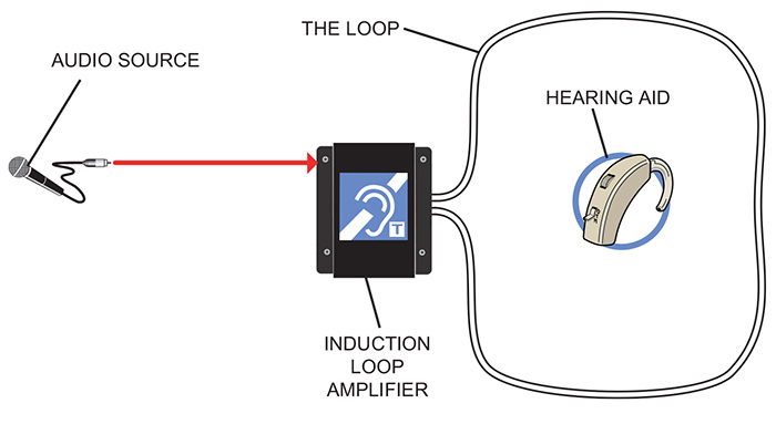
Induction loop systems do not use radio frequencies; they operate at audio frequencies.
The signal from an audio source is fed into an induction loop amplifier, which amplifies and sets the signal level in the same way as a conventional amplifier. The amplified signal, instead of going to a loudspeaker, is fed to a closed loop of cable that is normally placed around the perimeter of the room. Employing a constant current amplifier ensures the current is maintained at the set level whilst providing a flat frequency response without the need for equalisation circuitry.
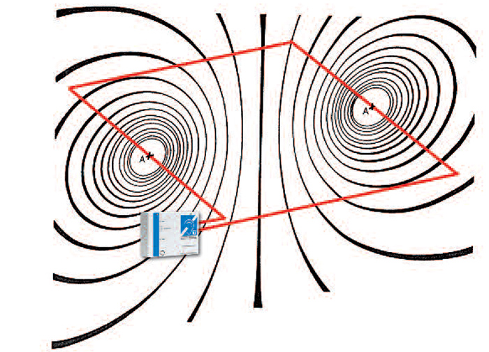
The current flowing through the loop generates a magnetic field that radiates in the space around the loop cable (see diagram below). Any lines of magnetic flux that pass through the telecoil in a receiver, such as a hearing aid, will generate a current in the coil that is then converted back to audio and fed into the listener’s ear.
In normal use, hearing aids utilise a microphone for amplifying localised speech. Whilst this is effective for local conversations/quiet environments, it is less effective for listening to speech or music at a distance. This is because the hearing aid’s microphone also picks up any background noise in the room and unwanted speech from other conversations. An induction loop system works by moving the required sound closer to the hearing aid via the hearing aid’s telecoil which is activated by turning it to the ‘T’ or ‘MT’ position.
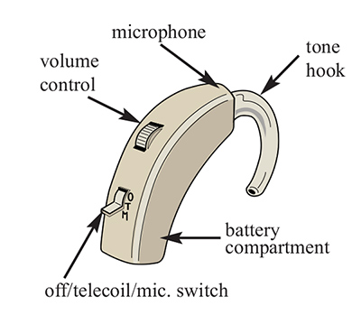
As telecoils are fitted as standard to most hearing aids (over 90% are said to have the ‘T’ position) induction loop systems can be considered cost-effective compared to other hearing assistance systems. Infrared systems, for example, require special receivers, the cost and maintenance of which must be met by the service provider.
Many modern hearing aids do not just amplify all frequencies equally; they are tailored to suit the user’s hearing problem and amplify different bands by different amounts. This gives maximum intelligibility, so the user has the best chance of understanding what is said.
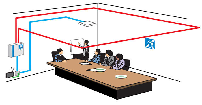
Induction loop systems are popular because:
– Unwanted sounds such as other conversations and background noise are not picked up.
-No special receivers are required – telecoils are fitted as standard in most hearing aids or are an inexpensive option.
-Magnetic induction tends to be more reliable and effective than other systems (infrared, for example, is line of sight only).
-Modern hearing aids amplify different bands by different amounts to suit a user’s specific hearing requirements.
The PDA range of induction loop equipment is one of the most comprehensive available, and is built in the UK where the use of loops is prevalent.
Before deciding which induction loop system to use, you first need to ascertain the size of the area to be covered in Square metres (m2). To calculate the size of the area in square metres, multiply the length by the width. For example, a room 6m x 6m in size would equal 36m2. The coverage provided by an AFILS amplifier is also quoted in square metres.
Designed to meet or exceed the requirements of the internationl standard EN60118-4 when correctly installed, all of the amplifiers in the PDA range offer excellent intelligibility, true current mode amplification, phantom power (for electret microphones).
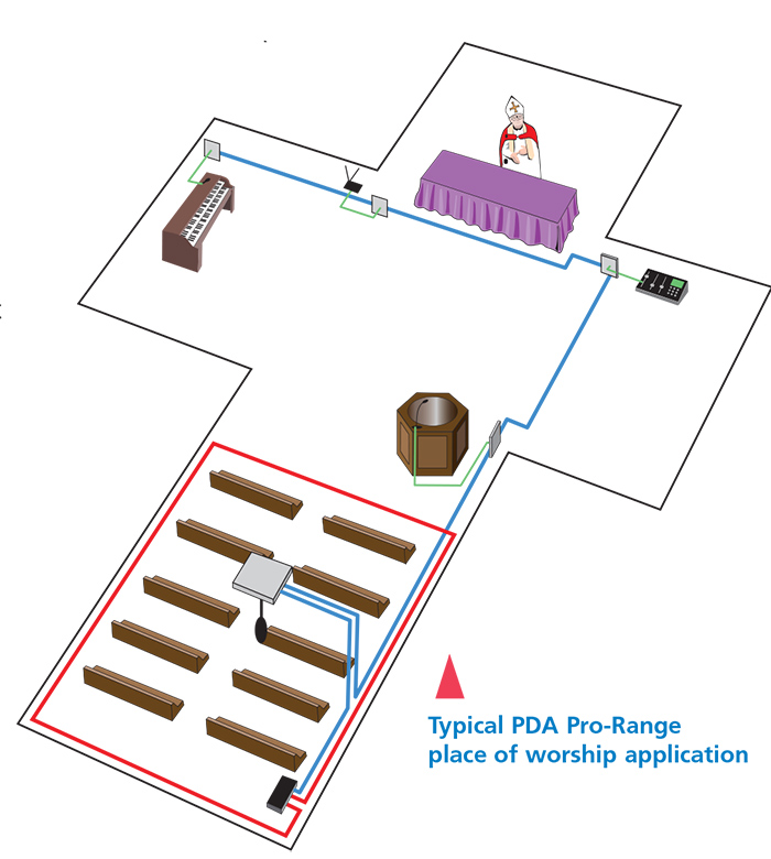
The PDA Pro Range of Induction Loop Amplifiers
– Ideal for theatres, cinemas, churches, conference halls and other applications where top quality sound is a must
– Each unit includes two XLR 3-pin input sockets (one balanced mic. and one switchable balanced mic./line) and one outreach connector.
– Adjustable level controls provided for all inputs – can be used individually or together as a three-input mixer
– Metal compensation control helps offset the frequency response problems associated with excessive metal in a building
– Includes a true output current meter and provides visual indication of the amplifier’s compressor action via two LEDs
– 3.5mm headphone socket allows true monitoring of the output signal
– Advanced audio signal processing with automatic gain control.
PDA200/2 – Up to 200m/sq
PDA500/2 – Up to 500m/sq
PDA1000/2 – Up to 1000m/sq
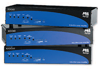
The PDA Pro-Range at a glance…
TYPE
Free-standing (optional wall or 2U 19” rack mount kits available); plugtop IEC mains lead provided
COVERAGE
200m2 (PDA200/2); 500m2 (PDA500/2); 900m2 (PDA1000/2)
DIMENSIONS
W 380 x H 80 (2U) x D 220mm; 3.74kg (PDA200/2), 3.46kg (PDA500/2); 4.54Kg (PDA1000/2)
INPUT
2 x XLR (one mic.; one mic/line) and one outreach connector
INDICATORS
Loop drive meter; compression (high/low); power on
CONTROLS
3 x input level controls, loop drive, metal compensation, on/off switch
What About The Induction loop cable?
There is nothing electrically special about induction loop cable. Almost any stranded or solid single core cable with tough insulation can be used, provided it is not liable to break (to minimise the chance of it shorting to earth and damaging the amplifier’s output) and is of the appropriate gauge and DC resistance (0.5 to 1 Ohm).
Auris can provide you with the correct size loop cable for the specified loop amplifier. If you are providing your own loop cable please refer to the loop cable selection chart below.
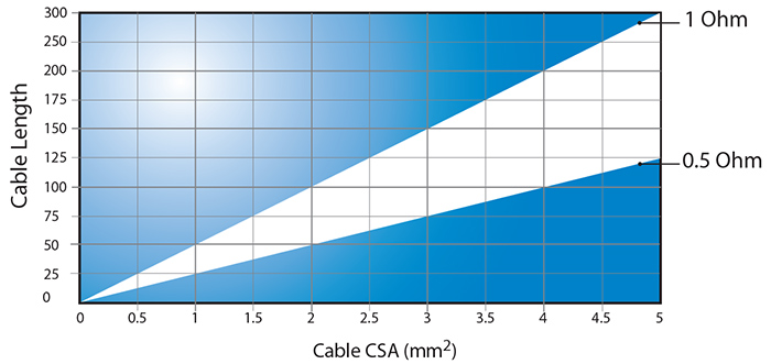
The chart shows the recommended CSA (cross-sectional area) for different lengths of loop cable. Simply work out the length of the loop required and choose a cable size that falls into the non-shaded area of the graph. For example, to cover a room 30m x 20m (600m2) the loop cable would need to be 100m long (2 sides @ 30m and 2 sides @ 20m). The recommended cable CSA for a loop this length is between 2mm2 and 4mm2. Therefore, a PDA1000/2 (which can cover areas up to 900m2) using 2.5mm2 cable would be sufficient.
Note that flat copper foil tape is also available and some installers prefer to use this as a floor loop under light duty carpets. Three sizes are available with cross sections of 0.5 mm2, 1.0mm2 and 1.5mm2. Protective tape will also be required to hold the cable down and reduce the likelihood of damage. Copper foil tape should be connected to the loop amplifier using solder or 1A ‘choc’ block.
Note that the chemical elements of some self-levelling floor compounds can react with the plastic covering of copper foil tape. If installing the loop under self levelling compound, we recommend you check their compatibility by covering a small piece of the tape with the compound to be used and look for any adverse reaction.
Induction loop system design and installation can be simple provided that a few basic facts are understood.
Maximum area coverage.
The approximate coverage provided by a loop amplifier is usually quoted in metres squared (m2). For example, the 120m2 quoted for our PDA200 amplifier means that the PDA200 can cover rooms up to 11 x 11m in size. The PDA range has amplifiers that can cover everything from a small chapel counter to a large 900m conference hall.
Note that in certain installations, it may not be necessary to cover the whole room, i.e., in a church there maybe designated seats.
Loop amplifier position
Induction loop amplifiers are best sited adjacent to the loop, as the feed cable will generate a magnetic field that may interfere with other areas. However, if a long feed cable cannot be avoided, the cable should be twisted to reduce magnetic radiation.
Loop cable position
It must be sited at least 600mm away from telephone, mains and control cables.
In most installations, loop cable is usually run around the perimeter (edge) of the room.
The field strength in the plane of the loop (the height at which the cable is positioned) varies greatly so it is best to install the loop above or below the listener at floor or ceiling height. The loop field will not be as strong but it will be much more even and provide better results. Do not mount the loop cable behind dado rails as the loop signal will be uncomfortably strong for the hearing aid user.
Typical listening height
Try to locate ceiling loops approximately 1.2m above the listener’s head (listening height with the hearing aid user sitting or standing is normally 1.2 to 1.8m from the floor). Note that when using a ceiling mounted loop, approximately 20% of the amplifier’s power will be lost for every 1.5m increase in height so the cable should never be mounted higher than 7m above listening height.
Structural steel, in particular, large sheets of metal (solid or perforated) such as metal suspended ceilings, can absorb the magnetic field resulting in uneven coverage or dead spots. To avoid the magnetic field being absorbed by structural steel, if possible keep the loop about a metre from large uprights.
If there is a steel-reinforcing grid in the floor, either put the loop in the ceiling or, if it must go in the floor, install the loop in plastic conduit as far above the grid as possible. The amplifier’s drive current may have to be turned up to overcome the effects of the metal, so choose the largest conductor size possible to suit the area.
If an application has a suspended ceiling with a metal grid and non-metallic ceiling tiles, tie- wrap the loop cable to the support wires a couple of centimetres above the tiles. If the tiles are metallic, the field strength will be affected, especially if they are electrically cross- bonded although it may be possible to partially overcome this by increasing the drive control on the amplifier. If single core cable fails to provide the required field strength in such applications, consider using three core cable and choc block to create three loops in series. Although this technique increases field strength it also reduces the top-end audio frequencies making the loop sound bass heavy, however this can be redressed using the metal compensation control on the PDA Pro-Range of amplifiers.
On floor loops, avoid running the loop up and over door openings as there will be a ‘dead spot’ (i.e. no signal) when the hearing aid user passes through. At doors and windows, the loop cable can pass vertically up and down either side. However, this wastes some power so care should be taken if the amplifier is only just capable of covering the area. Generally, we would suggest allowing 20% extra power in the amplifier if vertical runs are needed.
In applications with flat ceilings and sloping floors (cinemas, theatres, etc), try to run the loop at the same angle as the floor, perhaps behind a non-metallic handrail (if one is available) to ensure the signal is distributed evenly throughout the building.
Always run a trial loop and test to evaluate performance by listening to the signal with either a hearing aid or a dedicated loop listening device. To ensure the system complies with required standards, we recommend you also test the system using a pink noise generator and magnetic field strength meter.
Dead spots
In the region directly above or below the loop cable, the signal will drop to zero. This is because a hearing aid’s coil only responds to the vertical component of magnetic field. The higher the loop is placed, the wider the dead spot immediately over and under the cable will be.
Overspill
The signal generated by the induction loop will appear outside as well as inside the loop – sometimes up to three times the loop width away. This is often referred to as ‘overspill’. Similarly, a loop placed at ceiling height gives excellent coverage in the room above and a loop placed at floor level will cover the room below. Placing the downstairs loop in the floor and the upstairs loop in the ceiling will reduce the problem but if the loops are large the overspill may still be unacceptable.
The importance of overspill depends on the application. For instance, it will probably not matter if a church service can be picked up in the church grounds. However, should the signal from one loop system interfere with another in a multi-screen cinema, or a confidential loop signal in a police station be picked up by an unauthorised person in a neighbouring room, this is more concerning. There are more complex design solutions to prevent overspill that are effective. In many cases overspill can be reduced nearly as effectively and for much less cost using special loop patterns. Please contact us for details.
Mains hum
Some buildings have an underlying 50Hz hum present, especially old properties where live and neutral wiring takes separate routes, resulting in a loop. However, most hearing aids are designed to reject such low frequencies, and so this is not normally a practical problem.
Interference
Induction loops will interfere with other equipment, i.e., electric guitars will definitely pick up the magnetic field and cause feedback although some are less sensitive. If listeners can hear a hum when the loop system is operating, turn the amplifier off completely and test for noise using a hearing aid or a loop listening device. The noise should still be present and proves it cannot be due to the loop amplifier. We recommend this be tested for before installation.
Damage to the loop
A simple break can be repaired provided it can be found. All that matters is that the join is low resistance and allows the required current to flow through the loop. If the loop cable is shorted to earth, for instance, by drilling through it and touching a reinforcing grid, the amplifier output stage will be damaged. This cannot be protected against.
The isolation issue
When a hearing aid user switches his or her hearing aid to the ‘T’ position, its on-board microphone is switched off and the only noise that can be heard is the loop signal. If the system is connected to just one sound source, such as a TV, some hearing aid users say the lack of background noise makes them feel isolated. This can be overcome by positioning a microphone where it will convey background noise and pick up general conversation.
In summary…
Before designing a system, try to find answers to the following questions. Once you have the answers, the information in this guide will help you provide an effective solution.
• What is the area used for (reception, meeting room, lecture theatre, etc)?
• Do you require an audio input from a TV/Video? ! Do you require an input from an existing PA system?
• Do you require fixed or mobile microphones?
• How many microphone positions are required?
• Do any rooms next or close to the area require a separate system?
• What are the dimensions of the area – length, width and height?
• Where can the loop cable be installed – ceiling / floor void, in floor screed, under floor covering or wall?
• What is the ceiling height and how is it constructed?
• Is there any steel or other metals around the building?
• Is there any risk of theft to the equipment?
• Does it need to be a ‘secure’ system with little overspill?
Auras is based in Vernon, BC, and is run by Dave & Debbie Moore, who have many years of experience with specifying, installing & optimizing loop systems.
Before emigrating to Canada over 7 years ago, Dave & Debbie owned and ran DM Installation Projects and DM Music for Churches (www.dmmusic.com) in London, UK. They installed thousands of loop systems in public buildings, many in quite demanding heritage churches. They were surprised to find a lack of awareness of loop technology and its many benefits in Canada.
Having established a long & trustworthy business relationship with AVX loop systems in the UK, they approached the manufacturers Signet-AC to bring AVX loop systems to Canada. We are delighted to announce that Auris is the exclusive distributors of these AVX loop systems to Canada.
It was reported in the Hearing Review that 69% of the 183 models available had T-Coils fitted. The percentage in Europe is higher because there are loop systems everywhere. It’s ‘chicken and egg’ situation. New model cochlear implants also offer t-coils.
Some Hearing Aids can be retro-fitted with T-Coils, whilst others have them already fitted but not activated. Even those without hearing aids can use a portable loop receiver, although a bespoke hearing aid will have been adapted for the individual’s hearing loss which varies considerably.
There are many people who are hard of hearing that do not have hearing aids.
Sometimes it’s because hearing aids are cost prohibitive. Sometimes it’s purely vanity
that stops them. Infact, there are studies that confirm a 7 year procrastination period
before people act! For those people in transition, there is a battery powered RxTi
portable loop listener/receiver that can be used with headphones or earbuds.
For the small percentage of hearing aid users without t-coils, we suggest upgrading to a
unit with t-coils activated.
Venue Systems
Churches, Theatres, Cimema’s, Meeting & Conference Rooms,
Residential Homes, Council Chambers, Auditoriums etc
PDA 200 – Covers up to 200m sq
PDA 500 – Covers up to 500m sq
PDA 1000 – Covers up to 900m sq
Phased Array Loop systems for larger and specialized design (See Vernon Performing
Arts Case Study).
Domestic – DL50 kit – Covers up to 50m sq
Counter – CL1 kit – Includes amp, pre formed cable & microphone
Vehicle – VL1 – Includes amp, cable, cigar lighter power supply & microphone
Portable – PL1 kit – include rechargeable battery, integral mic
Portable Loop Listener/Receiver – RxT1